Building the Benchwork
Strong benchwork is essential for reliable operation! Strong benchwork does not, however, mean using 2x4 lumber! Read along as I explain how I made my benchwork from lightweight materials that could support my (200lb) weight.
 Modular Benchwork Design
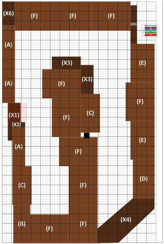
I started with my original sketch and placed "standard frames" between the wall and the edge of the aisles. I found that I could work with 6 common frame sizes, and 6 "odd" sizes. The standard frames were 48" long and ranged from 15 to 30" deep. Odd frames were less than 48" long.
Benchwork Frames
By creating standard frames, I could pre-create most of them in my workshop and easily carry them to the basement train room. I used three sheets of 1/2" cabinet grade plywood (smooth finish one side) and cut them into strips 3-7/8" wide by 48" long. These formed the long side of the standard frames. I carefully planned the cuts for the short sides to minimize waste, and the short cut-offs were cut to squares, then were halved diagonally to form triangles to create small corner braces. The sides and ends were glued and secured with an air stapler, and the corner braces were glued in place. The deep (30") frames received a 1x4 center cross-brace that was glued and stapled. Once dry, these were carried to the train room. These were light enough that my 7-year-old granddaughter helped me carry them to the train room and put them into position!
Wall Mounting
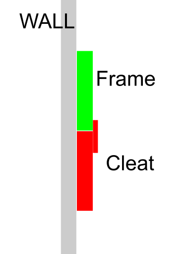
To mount the frames to the walls, I used a modified "French Cleat" method. A normal French Cleat
 Wall Cleat
simply rips a piece of lumber down the middle at a 45-degree angle, the up-angle part is secured to the wall and the down-angle secured to the movable item. Instead, I used a laser level to set a precise height on the walls and secured a piece of 1x3 furring strip to the wall on that line. Furring strips are rough-cut lumber and are inexpensive. I ran my strips through a planer to ensure that the side facing the wall was flat, and then trimmed the top edge flat on my table saw. The frames now lay squarely on these rails. I used either short pieces of lattice (1/4" thick by 1.25" wide - 6" long) or metal reinforcement plates and screwed them to the wall strip, which kept the frame secured onto the support strip yet easily removed or adjusted. The drawing shows how the cleat attaches to the wall and supports the rear of the frame. The "hook" on the cleat allows the frame to slide side to side for adjustment. The frame remains loose, but can be secured if necessary.
Once the frame is attached to the cleat, I used a piece of scrap 1x2 and clamped it to support the other end, then positioned the next frame. Frames were clamped together in each corner.
Legs
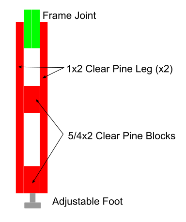 Leg Design - not to scale!
The ends of the frames facing the aisles as well as the peninsula needed to be supported with legs. This was the only "quality" lumber that I purchased. An 8 foot clear pine 1x2 was cut in half to form two sides of one leg. I used two blocks of 5/4x2 lumber 4-inches long and glued them to the bottom and the middle of each 48" pair of leg parts, resulting in a single leg that was open at one end and closed in the center and opposite end. I drilled a hole in the bottom block to insert an adjustable foot to aid in leveling the frame. You can see that this design allows the leg to straddle two frames where they join.
Once the legs were prepared, I set them over the frame joints, leveled them vertically and the frame horizontally and clamped them in place. I then drilled a 1/4" hole completely through the leg and both frames and secured it with a 1/4-20 bolt and nut. I used 3" bolts to attach the legs, and 1.5" bolts to connect the frames. Each frame had two 1/4" holes drilled a few inches from each corner and they were secured with 1/4-20 bolts, washers, and wing nuts. After the first leg bolt was secured, I removed the clamp and added a second bolt, which resulted in a fairly secure stance.
For the legs on the peninsula, I used the same method but added a 45-degree brace using 5/4 square material, cut to 45-degrees on each end. I glued this into the leg just above the middle brace, then added a small screw through the ends (pre-drilling and counter-sinking the hole) - securing the brace to the leg and to the frames. I continued with this process until all of the frames were connected together and legs were installed.
At this point, the benchwork was ready to have the top layer applied, which would significantly enhance the strength of the design. But first...
Wiring
I'm going to address wiring in a separate installment, but this was the time I chose to run most of the feed cables. It was far easier to pass the wires through cable rings by reaching through the open top instead of reaching below the table! I knew I needed 10 main feeds for 8 power districts, so I pulled these cables and installed the brackets for the distribution terminals.
Topping Out
The last step of the benchwork installation was laying down a 1/2" plywood top. I started by gluing 5/4x2 blocks near each inside corner of the frames to provide a solid target for the screws. Once these were secure, I laid a 4x8 sheet of plywood over the benchwork, drilled holes where the blocks were, and secured the plywood to the frames. Once the plywood was screwed down I printed my AnyRail onto 4 sheets of paper with a grid and mapped out the edge of the aisles. The excess plywood was trimmed along these lines with a jig saw.
At this point, the benchwork was solid and strong enough to support my weight on the peninsula. Next step - the foam and cork base!
Follow-up
Just to show that good planning pays dividends, when all of the benchwork frames were created and then assembled, only one piece - X5 - needed adjustment, and that was due to the wall where it was placed not being perfectly square! Creating the frames took a weekend, and all of the benchwork was installed the following weekend. Plywood was applied and trimmed in another weekend but a few weeks later due to time spent planning and pre-installing the main buss wires.
Photo Gallery
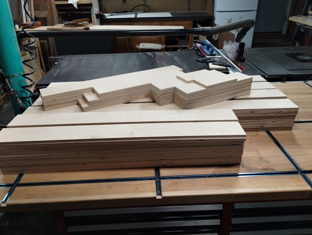 The pre-cut frame boards stacked in the workshop, ready for assembly.
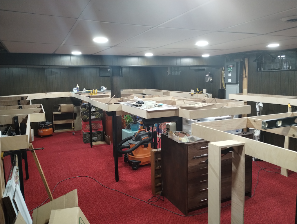
 All of the frames, built and staged in the layout room.
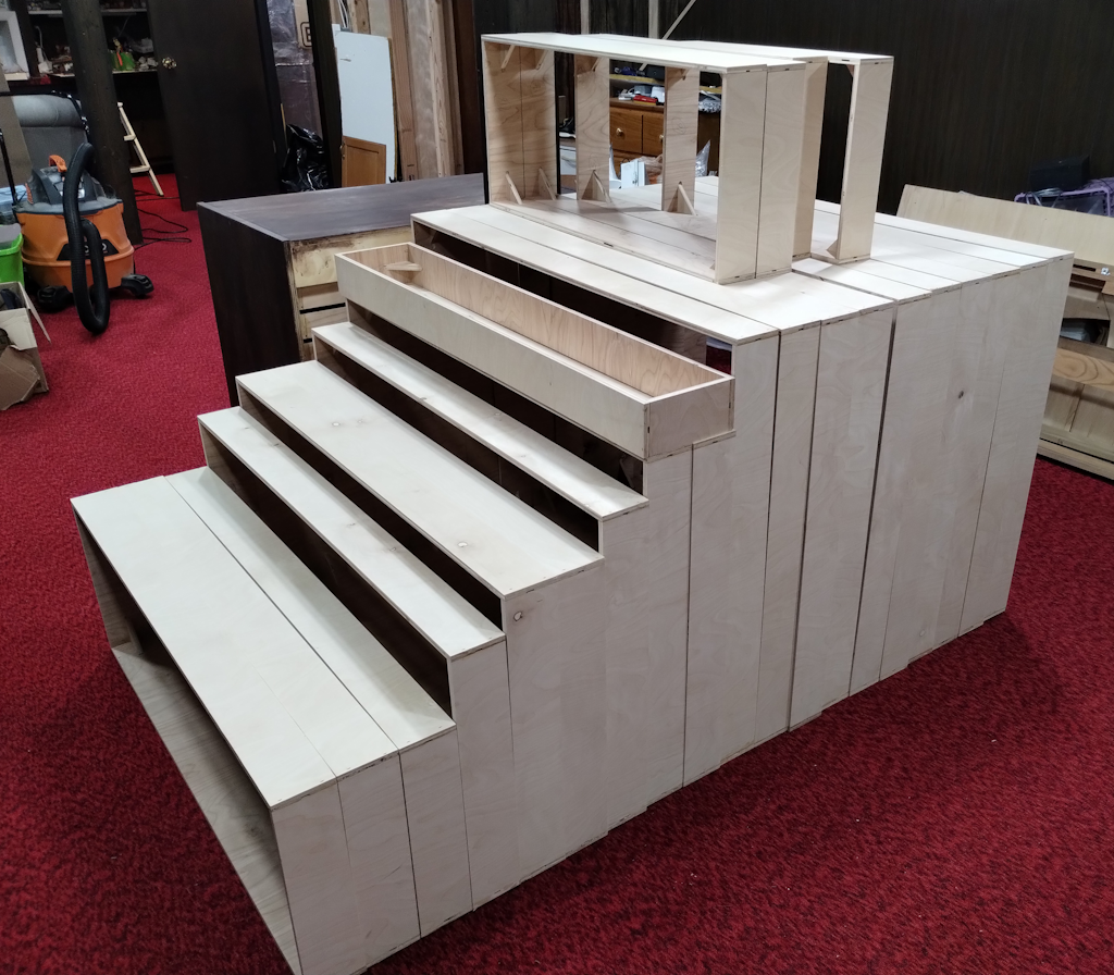
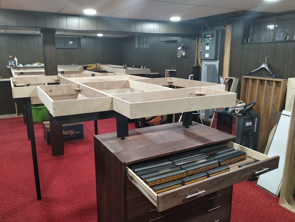 The first frames assembled, legs installed, and the peninsula end supported by the car storage cabinet.
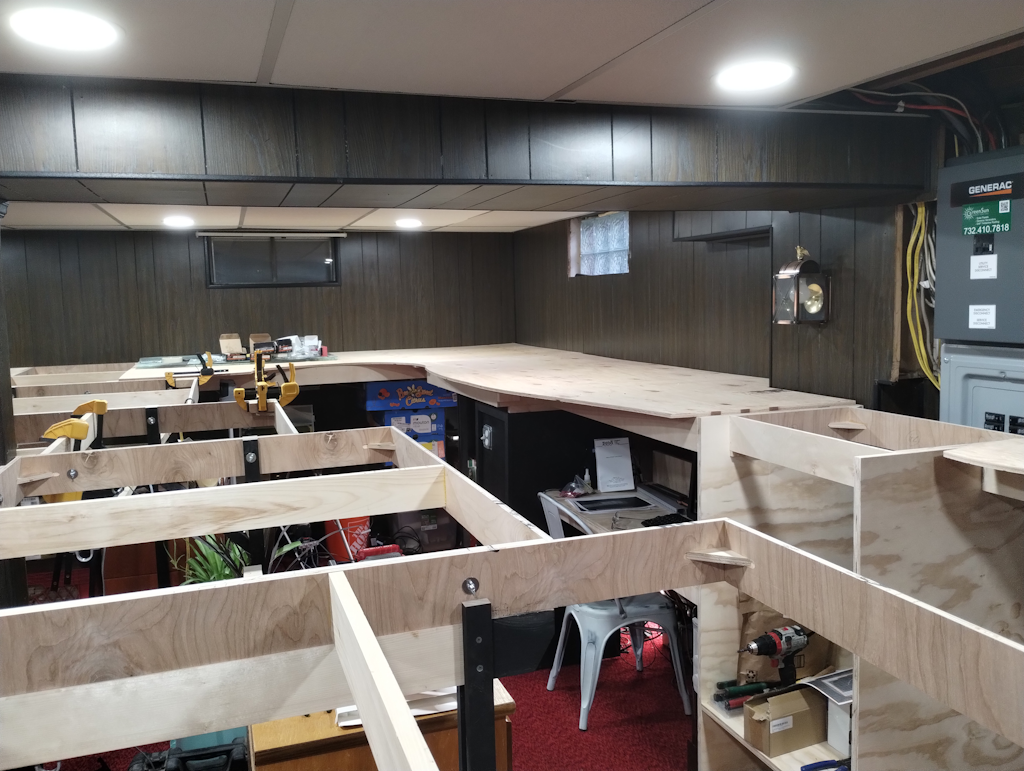 Peninsula and right side frames complete, first plywood top installed and cut. Note electronics cabinet, programming/JMRI station, and removable panel at the electric panel.
 Just one more frame to install!
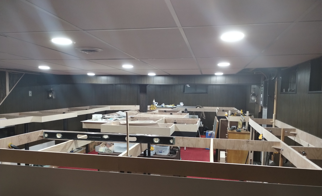
 Another view of the frames before the last one is installed.
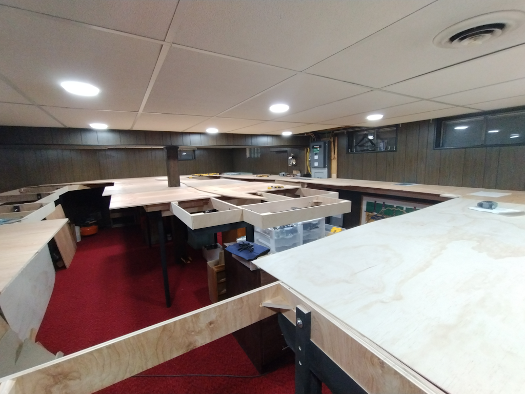 Last frame installed, much of the plywood installed.
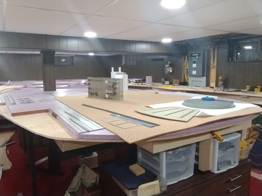 Plywood is down, foam being applied, and cork and structures being test-fit for position.